by: Debjyoti Chatterjee and Nathan Baeckeland
This blog post focuses on one major challenge of the GFM inverter: its limited overcurrent handling capability. During normal grid operations, GFM inverters perform seamlessly, emulating traditional grid behavior through their precise control algorithms. However, grid disturbances such as short circuits, voltage sags, or abrupt load changes pose a significant challenge. These events can cause a surge of electrical current that exceeds the design limits of the inverter’s semiconductor-based power stage. Left unchecked, such surges can damage the inverter and compromise the grid’s stability.
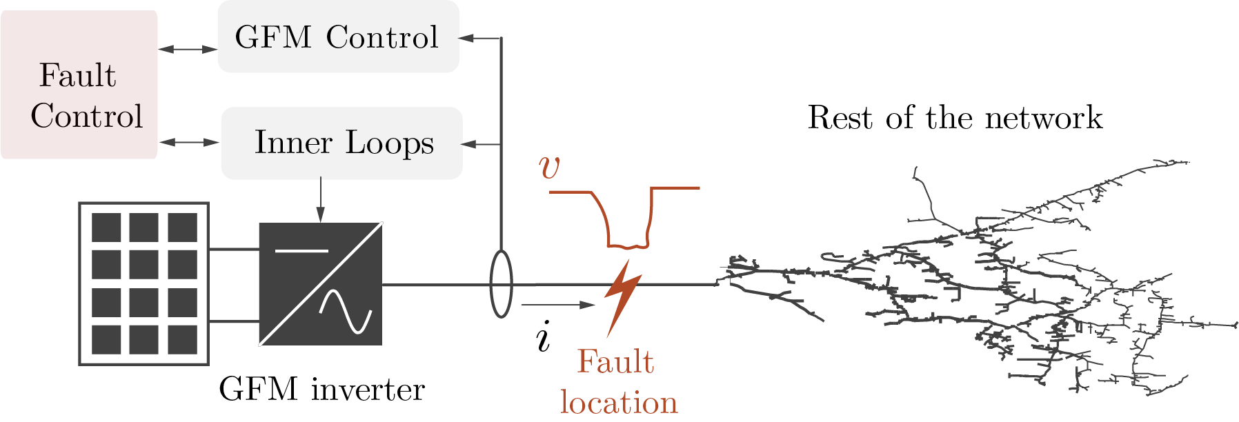
Figure 1: GFM inverters require an additional fault current management system to limit overcurrent and ensure stability during a disturbance
Unlike their synchronous-generator counterparts, which can handle high fault currents due to their high thermal inertia, GFM inverters are far more sensitive. Their fault-current contribution is limited by the thermal and electrical constraints of their power electronics components. This limitation complicates not just the protection of the inverters themselves but also the effectiveness of grid-wide protection schemes, which historically relied on high fault-current magnitudes to detect and isolate grid faults. Therefore, as shown in Fig. 1, overcurrent management is a critical consideration in GFM inverter design.
How Current Limiters Work
Without proper safeguards, excessive currents during disturbances can damage the inverter’s power stage, leading to system failures and jeopardizing grid stability. Addressing this challenge is where current limiters come into play. Current limiters are the first line of defense during grid disturbances. These devices regulate the flow of electrical current, ensuring it remains within safe operational limits. There are three main approaches to current limiting in GFM inverters: direct, indirect, and hybrid methods. These current limiters can be implemented at different stages, as shown in Fig. 2.
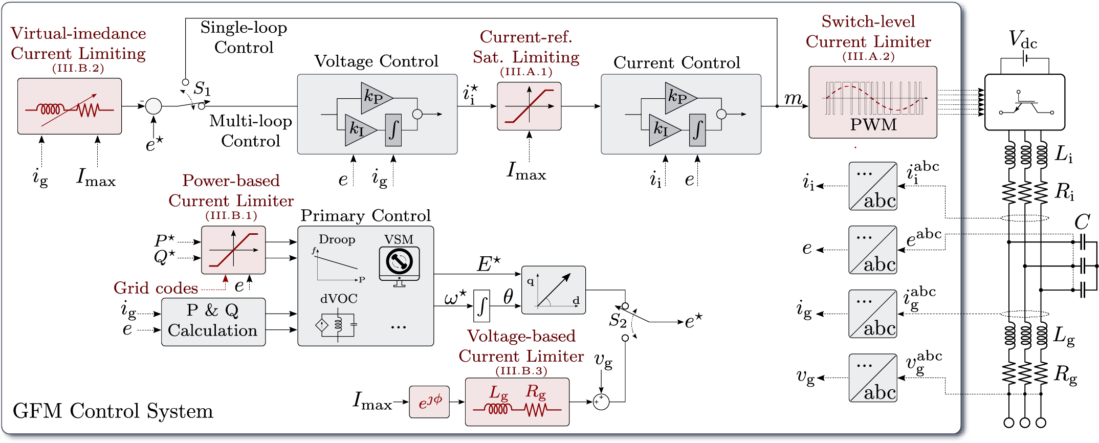
Figure 2: Overview of direct and indirect current-limiting methods for GFM inverters
- Direct Current Limiting: In this approach, the limiter directly caps the output current of the inverter. Techniques like current-reference saturation are commonly used, which dynamically scale down the current commands to prevent excessive output. This method is highly effective for immediate response to rapid fault-current surges.
- Indirect Current Limiting: Instead of directly limiting the current, indirect methods adjust other control variables, such as voltage or power references, to indirectly reduce the current flow. Virtual impedance techniques, for instance, introduce a simulated resistance or reactance to the inverter’s output, effectively curbing the fault current while preserving the inverter’s voltage-source behavior.
- Hybrid Current Limiting: Hybrid approaches combine the strengths of direct and indirect methods. For instance, a hybrid limiter might use direct limiting to provide rapid fault-current control, followed by an indirect method to stabilize voltage and frequency. These designs are particularly effective in maintaining system stability during extended disturbances while safeguarding the inverter hardware.
System-Level Impacts: Transient Stability
Current limiters do more than just protect the inverter; they also shape the way these devices interact with the grid during and after disturbances. The design and implementation of current limiters have far-reaching implications for grid stability and reliability, specifically on transient stability, voltage and reactive power support, post-fault recovery, and grid resynchronization. Major device and system-level impacts of current limiters are shown in Fig. 3.
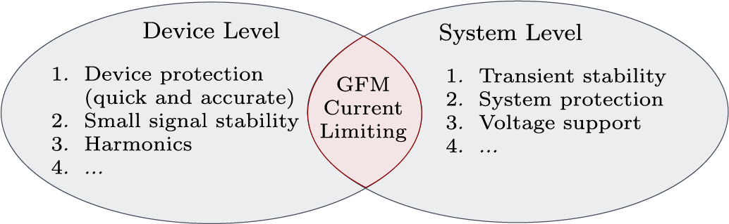
Figure 3: Graphical representation of the challenges facing current limiting in GFM inverters both on device level and system level
In the early days of interconnected power systems during the 1920s and 1930s, engineers faced a pressing challenge: ensuring generators stayed stable after disturbances. Transient stability became a critical focus, but without advanced computers, they needed practical tools for quick analysis. This led to the development of the Equal Area Criterion (EAC), a clever graphical method introduced to study stability in simple systems like single-machine infinite bus (SMIB) setups. The EAC was formalized and popularized in the 1930s and 1940s as it provides an intuitive graphical method to evaluate stability by visualizing the accelerating and decelerating energy areas on a power-angle (P-δ) curve. After World War II, the rapid expansion of electrical grids and the introduction of large centralized generation systems solidified the importance of transient stability studies. With the advent of computers in the 1960s and 1970s, numerical simulations began to dominate transient stability analysis. However, the EAC remained widely used for teaching, conceptual understanding, and quick assessments in single-machine studies.
In synchronous machines, the P-δ curve is determined by the mechanical and electrical power exchange. For GFM inverters, the dynamics differ because they rely on current limiters during disturbances. The impact of current limiters on transient stability can be well understood by studying how the current limiters impact the P-δ curves. Direct current limiters restrict the output current, effectively truncating the P-δ curve. This can reduce the system’s ability to recover from large disturbances, as the truncated curve limits the area available for deceleration energy. Conversely, indirect limiters, like virtual impedance, preserve the P-δ curve’s continuity, offering better support for transient stability by allowing more natural power exchange dynamics.
These insights are shaping new methods to apply EAC concepts to inverter-dominated grids. For example, researchers are exploring ways to adapt the P-δ framework to include the effects of current limiting, enabling more accurate stability assessments in modern systems. This work is particularly significant as grid operators transition to inverter-heavy networks, where classical stability tools require reevaluation.
Impact on Power System Protection
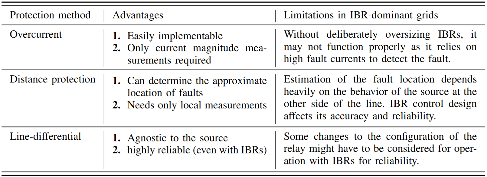
Power system protection in grids dominated by inverter-based resources (IBRs) faces unprecedented challenges. Unlike synchronous generators, which produce high fault currents, inverters are limited by hardware constraints, offering only marginal overcurrents during faults. This disrupts traditional protection schemes such as overcurrent, distance, and directional protection.
- Overcurrent Protection: Conventional overcurrent protection relies on significant fault currents for fault detection and isolation. Inverter-based systems often struggle here due to their limited short-circuit capabilities. GFM inverters, however, can mitigate this limitation by proactively providing maximum available current during faults, thus enhancing the detectability of faults. Adaptive overcurrent protection schemes are being explored to address these limitations.
- Distance Protection: Distance protection, which calculates the impedance between a fault and a relay, faces challenges with IBRs. The inverter’s current limiter, through its control algorithms, can alter the phase angle of the fault current, leading to erroneous impedance calculations. However, studies have shown that with specific current limiter designs—such as highly inductive virtual impedance—GFM inverters can emulate the behavior of synchronous generators, enabling distance protection to function effectively even in mixed IBR and synchronous generator systems.
- Line-Differential Protection: Unlike overcurrent and distance protection, line-differential protection compares currents at both ends of a line to detect anomalies. This method remains reliable in inverter-dominated grids as it is source-agnostic, though high-bandwidth communication and relay setting adjustments may be necessary.
Table I: Comparison of Protection Methods for Inverter-Dominant Grids
To overcome these challenges, grid operators and researchers are investigating adaptive and flexible protection schemes tailored to the unique behaviors of GFM inverters. Such strategies will ensure that inverter-heavy grids can maintain reliability and resilience while accommodating the growing share of renewable energy.
Striking the Right Balance
The design of current limiters is a delicate exercise in balancing multiple objectives. On the one hand, limiters must act quickly to protect inverter hardware from thermal damage. On the other hand, they need to maintain grid stability and facilitate post-fault recovery. This dual purpose often results in trade-offs that require careful consideration.
Direct current limiting methods are highly effective at curbing fault currents instantaneously, but they may disrupt the voltage-source nature of GFM inverters during faults. Conversely, indirect methods, like virtual impedance, are better at retaining the voltage-source characteristics, which aids transient stability and synchronization. However, these methods may not utilize the full overcurrent capability of the inverter, which could lead to missed opportunities for grid support.
Recent advances point toward hybrid current limiters as a promising solution. By combining the strengths of direct and indirect approaches, hybrid limiters can offer fast fault response alongside improved stability and synchronization. For example, integrating a fast-acting direct limiter for immediate protection with a virtual impedance mechanism for transient stability ensures a balanced approach to current limiting. Additionally, enhancements such as anti-windup feedback loops and adaptive designs further improve the dynamic performance of hybrid limiters.
Nevertheless, challenges remain. Developing a single limiter design that excels in all scenarios is complex if not impossible. Hardware constraints, grid code requirements, and evolving grid dynamics make it essential to adopt flexible and customizable current-limiting solutions. Collaborative efforts between researchers, system operators, and manufacturers are vital to refine these technologies.
The Road Ahead
As the global energy mix shifts toward higher penetration of renewables, the role of current limiters in GFM inverters will become even more critical. Future grids will depend heavily on inverter-based resources operating under diverse and often extreme conditions. Consequently, ensuring robust and adaptable current-limiting strategies is paramount. Some of the potential future work directions include:
- Power System Protection: Developing solutions for power system protection that incorporate the current-limiting behavior of GFM inverters will require more focused research. Enhancing compatibility with legacy protection schemes and designing novel approaches tailored to GFM systems will be critical.
- Transient Stability in Multi-Inverter Systems: Future grids will feature thousands, if not millions, of GFM inverters coexisting with other generation assets. Understanding how various GFM current-limiting and fault-behavior strategies interact with each other and other sources in terms of system stability and protection is critical but largely uncharted.
- Grid Code Revisions: Revising grid codes to explicitly address the performance expectations of GFM inverters during faults and disturbances is essential. Clearly defined guidelines will help streamline the integration of these technologies into existing and future power systems.
In summary, current limiters are not just protective measures; they are enablers of a reliable, renewable-powered future. By ensuring GFM inverters can operate safely and effectively under all conditions, they pave the way for a grid that is both resilient and sustainable.
Recommended Reading
This blog is an excerpt from the recently published paper: N. Baeckeland, D. Chatterjee, M. Lu, B. Johnson, and G.-S. Seo, “Overcurrent Limiting in Grid-Forming Inverters: A Comprehensive Review and Discussion,” in IEEE Transactions on Power Electronics, vol. 39, no. 11, pp. 14493-14517, Nov. 2024, doi: 10.1109/TPEL.2024.3430316. If this article has sparked your curiosity, we recommend reading the full paper for an in-depth exploration of current limiters in grid-forming inverters and their system-level impacts!